- Color – a color well (click to change)
- Name [ model-name ]
- Radius (default 2.0 Å)
- Length method
- Enclose atom/point projections (default)
– span the two points
- Length padding (default 0.0 Å) – additional length on each end
- Fixed value
- Length (default 10.0 Å)
- Enclose atom/point projections (default)
– span the two points
Only one color-well color, fixed radius, and fixed length can be given at a time, but axes with different values can be created in successive uses of the tool. Clicking Apply (or OK, which also closes the dialog) calculates the axes, adds them to the table, and generates the corresponding objects. Axis parameters are reported in the Log.
Planes
Clicking Define plane... opens a dialog for defining a plane based on the selected atoms (the equivalent command is define plane). Eigenvectors/values are calculated from the atomic coordinates after subtracting the position of their non-mass-weighted centroid. The plane is anchored at the centroid and aligned with the two largest eigenvectors (the third-largest eigenvector is normal to the plane).
- Plane name [ name ]
- Color
- atom-based (default)
– the most prevalent color among the atoms used to define the plane,
if at least 30% share that color, otherwise #909090
- a color well (click to change)
- atom-based (default)
– the most prevalent color among the atoms used to define the plane,
if at least 30% share that color, otherwise #909090
- Radius method
- Enclose atom projections (default)
– span the projections of the atoms used to define the plane
- Extra radius (padding) (default 0.0 Å)
- Fixed value
- Radius (default 10.0 Å)
- Enclose atom projections (default)
– span the projections of the atoms used to define the plane
- Disk thickness (default 0.10 Å)
Clicking Apply (or OK, which also closes the dialog) calculates the plane, adds it to the table, and generates the corresponding object. Plane parameters are reported in the Log.
Centroids
Clicking Define centroid... opens a dialog for defining a centroid based on the selected atoms (the equivalent command is define centroid).
- Centroid name [ name ]
- Color
- atom-based (default)
– the most prevalent color among the atoms used to define the centroid,
if at least 30% share that color, otherwise #909090
- a color well (click to change)
- atom-based (default)
– the most prevalent color among the atoms used to define the centroid,
if at least 30% share that color, otherwise #909090
- Radius (default 2.0 Å)
- Mass weighting (default off) – whether to use mass weighting, i.e., to define the centroid as the center of mass rather than center of geometry. The radius of a marker (Å) is used as its “mass” (daltons).
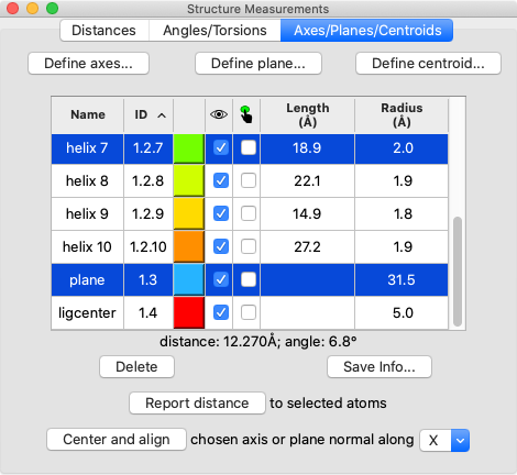
Axes/Planes/Centroids Table of Objects
The table of objects includes the following columns, many the same as in the Model Panel:
 |
- Name – model name; doubleclick to edit
- ID – model number; doubleclick to edit
- a color well; click to change color interactively
 – show/hide checkbox
 – selection checkbox
- Length
- Radius
Clicking a column header sorts the table by that column, and the table can be saved as a comma- or tab-separated file by choosing Save CSV or TSV File... from the dialog's context menu.
One or more objects can be chosen from the list by clicking and dragging with the left mouse button; Ctrl-click (or command-click if using a Mac) toggles whether an object is chosen. Chosen lines are highlighted in the dialog.
Clicking Delete removes the chosen objects.
Choosing any two objects reports their applicable geometric relationships below the table and in the Log. For angle measurements, axes and planes are treated as infinite. For distance measurements, axes are treated as finite line segments, while planes are treated as infinite.
Report distance measures distances between the chosen objects and selected atoms; the minimum, maximum, and mean distances to each chosen object are reported in the Log.
Center and align is available when a single axis or plane object is chosen. It centers and aligns the chosen axis, or centers the chosen plane and aligns its normal vector, along the specified direction in screen coordinates:
- X – horizontal in the plane of the screen
- Y – vertical in the plane of the screen
- Z – perpendicular to the screen, along the line of sight
turn y 180 center #1.2.3
Clicking Save Info... writes all axis/plane/centroid information to a file, regardless of which objects are chosen in the table. For each object, the information includes model name, model ID, and untransformed center coordinates (xc,yc,zc). Axis information also includes length and direction (orientation) expressed as a unit vector (xu,yu,zu). Axis endpoint coordinates (x1,y1,z1) (x2,y2,z2) can be generated as follows:
|
x1 = xc – 0.5(length)(xu)
y1 = yc – 0.5(length)(yu) z1 = zc – 0.5(length)(zu) |
x2 = xc + 0.5(length)(xu)
y2 = yc + 0.5(length)(yu) z2 = zc + 0.5(length)(zu) |
Plane information also includes radius and orientation expressed as a normal unit vector.
UCSF Resource for Biocomputing, Visualization, and Informatics / February 2024